|
The Router (TRB001)
comes with a collet wrench, a straight
cutter, a ¼" collet reducer, a
metal baseplate with fence attachment and
a ten-page instruction booklet. The front
cover of the booklet included the
following declaration:
IMPORTANT
This router has a number of unique
features. Even if you are familiar
with routers, please read this
manual to make sure you get the
full benefits of the unique
design. |
This is well worth the time spent, in
order to be able to confidently switch
between the different plunge modes, set
the depth stop and attach the fence
without any problems. All of these
functions have really been well thought
out and are impressive in both design and
ease of execution.
Here's an overview of the router, both
front and rear views, with the main
features numbered.
N.B: The wing nut on the metal
baseplate is part of the trammel
(compass) facility, described later.
 |
Front View
- Fully enclosed safety
shields (remain fitted when
changing bits).
- Illuminated switch with
shutter to prevent accidental
starting.
- Powerful 3¼HP motor
with soft start.
- Easy to set turret stops
with direct reading
calibrations.
- Multi-function fence.
Incorporates extended
baseplate and circle cutting
features.
- Variable speed (8,000 to
20,000 rpm) with speed
maintenance under load.
- Removable plunge spring
reduces plunge resistence when
table-mounted.
- Plunge locking lever.
|
 |
Rear view
- Winder handle
rack-and-pinion plunge for
fast depth adjustment.
- Conversion switch for plunge
or winder depth setting.
- Micro-winder for precise
depth setting through the full
range.
- Large bore dust port for
effective chip extraction.
- ½" collet (with
¼" reducer).
- Shaft lock automatically
engages in cutter change mode.
- Triton ½" Premium TCT
Router Bit included.
|
 |
This is a big machine, but not
heavy for its size, weighing in at
6Kg (13.2 lbs.). Being designed
for use in a router table (part of
the Triton system), it has a
couple of features that are
particularly useful for table
mounting. The first is that the
plunge spring is easily
removeable, so that you don't have
to fight the spring when trying to
adjust the height.
To remove the plunge spring you
slacken the screw which secures
the spring cap - located above
the right-hand column - then
carefully turn the cap
anti-clockwise (about an eighth
of a turn to release the bayonet
fitting), making sure to keep
downward pressure to hold the
spring. Once the cap has cleared
the fitting, you can slowly
release the spring from its
housing.
The cap has a central rod to
prevent the top of the spring
deforming when being replaced
and it is a simple matter to
return the spring and engage the
bayonet fitting.
Also visible is the dust
extraction port, which has a
left-hand thread of 38mm outside
diameter (the adaptor fitted is
mine).
|
| The second feature is that the
plunge depth allows the collet to
extend past the router base when
fully plunged, as shown here. This
is useful for bit-changing
generally, but becomes especially
useful and convenient for
bit-changing whilst table-mounted.
When the router is fully
plunged, the spindle lock is
automatically engaged and the
power switch is by-passed so
that the machine cannot be
operated in this position, even
accidentally.
|
 |
 |
The router has a rack and pinion
mechanism built into the
right-hand column - rear view
shown here. This enables the
router height to be adjusted by
turning the right-hand handle when
using the rack and pinion. This is
both simple and effective in use
and when mounted in a router table
it is particularly brilliant! The
router can be wound up or down
with ease, especially with the
plunge spring removed.
Also in this picture you can
see the spindle lock cam
protruding from the main body.
As the router reaches its full
plunge depth the cam is
activated, which will engage the
spindle lock in one of four
indents in the rotor as soon as
the main shaft is turned. As
stated previously, the power is
by-passed when in this position,
so there is no possibility of
the motor being switched on with
the spindle lock engaged.
|
| Both handles are round, smooth
and easy to grip. Here is an
operator's view of the right-hand
handle with the rack and pinion
ring lock in the engaged position. |
 |
 |
This is the grip used to release
the ring lock manually and turn
the handle to raise or lower the
router height. Once the desired
height is reached, release the
ring and the machine is locked at
that height. |
| The height adjustment has a
number of "steps" throughout its
range and these may not fall
exactly at the height you require.
The micro-adjuster knob is used to
set the height accurately and can
be used at any of the "steps" when
using the rack and pinion plunge
method.
This means that
micro-adjustment is available
over the full plunge depth, but
without the need to "take up
loads of slack" when the router
is plunged deeply.
Also seen in this picture is
the plunge spring cap release
screw in its unlocked position -
the spring cap's bayonet fitting
continues to retain the spring.
|
 |
 |
Here is the plunge lock lever,
easily reached by the operator's
right thumb. This is a
conventional plunge lock when in
"free plunge mode" and an extra
lock when in rack and pinion mode
(recommended for heavy cuts).
I have operated the machine
without using it and the rack
and pinion mechanism held
totally secure. However,
engaging the plunge lock lever
is best practice, as it is
possible to grip the right-hand
handle ring lock when operating
the router (although not a
"natural" motion) and if this
was squeezed too hard it could
engage the rack and pinion.
When used in a router table,
the rack and pinion and the
micro-adjuster set the height
perfectly. The plunge lock lever
in this situation is "belt and
braces" when rounding over and
profiling with small cutters,
but I found myself using it (as
best practice) when raising
panels with a large bit.
The lever is adjustable for
operator comfort and preference.
I left mine as it was when I
unpacked it, as I find it ideal
where it is.
|
| Having described the rack and
pinion plunge method, together
with its micro-adjuster, the
Triton router also has a
conventional free plunge action.
This is operated by locking out
the rack and pinion with the
plunge mode selector, which is
built into the end of the
right-hand handle. To disengage
the rack and pinion mode, the
selector is turned in a
clockwise direction, then
pressed inwards and turned
clockwise until it clicks in.
Now the router is free to
plunge conventionally, using the
plunge lock lever to lock the
height if desired.
|
 |
 |
The plunge depth turret is also
an ingenious design. It consists
of a sprung-loaded tube,
controlled by a depth stop locking
knob (out of focus in this picture
- sorry!). The turret itself has
two adjustable posts and one
reference post (shown here with
the plunge stop rod in contact
with it).
Suppose that you need to rout
some 5mm holes for adjustable
shelf pins, using a jig.
Previously, I had to measure the
jig thickness, add the depth of
the hole (7mm) then set that
depth on the turret by lowering
an adjustable scale, then
locking it.
With the Triton, nothing could
be simpler - I set up the jig,
insert the router into position,
loosen the locking knob and
plunge the router until the
cutter comes into contact with
the workpiece. With the plunge
stop rod in contact with the
reference part of the turret, I
lock the knob. Now I have a
"zero datum" set, so I just need
to rotate one of the two
alternative adjustable turret
post stops to my required
plunge, in this case, to 7mm.
Once I've done that, I rotate
that post under the plunge stop
rod and begin routing. Ingenious,
effective and simple.
Without reading the booklet
before using the tool, I might
have spent a bit more time
head-scratching, but as soon as
I read it and looked at the way
it worked, I was able to set it
right first time and it's
spot-on accurate too.
|
| Here's a closer look at the
plunge depth stop turret. The
plunge depth rod is in contact
with the reference post section of
the turret.
You can see that there are two
posts with adjustable
thumbwheels, so you can set two
different or alternative depths
if you need to, for incremental
plunge depths, for example.
The scales are easy to read and
the measurements are accurate.
The turret pivots easily, but
the indents hold each of the
three positions firmly.
|
 |
 |
The On/Off switch is robust,
very safe and another example of
thoughful design. In the "Off"
position (shown here), the switch
is covered by a sliding shutter.
The shutter is see-through and the
power switch illuminates (red)
when power is connected - whether
the switch is on or off. |
| To operate the switch, slide the
shutter towards the rear (to the
left in this picture) and depress
the lower part of the rocker
switch. This action rotates the
upper part of the switch into the
plane of the sliding shutter, thus
keeping it open whilst the switch
is on.
As soon as the rocker switch is
turned off, the sliding shutter
returns to its safe covering
position.
The switch is locked out when
the router is fully plunged in
order to fit or remove a cutter.
When using a router in a table,
it is normal to switch power on
and off via a remote switch.
This is possible with the
Triton, but there is another
benefit to the switch design,
because with the switch in the
"On" position it is impossible
to plunge the router into the
cutter change position.
Therefore, not only does the
switch not allow the router to
be switched on (even
accidentally) when changing
cutters, it will not allow an
operator to get into the cutter
change position when the switch
is on - even though the power is
off. Now that's what I call safe!
|
 |
 |
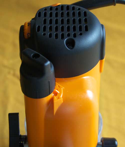
The variable speed is controlled
by this thumbwheel built into the
motor cover. It is numbered 1
through 5 for reference, although
speed changes are stepless. The
reference numbers approximate to
the following RPM:
- 8,000
- 10,000
- 14,000
- 18,000
- 20,000
Below the speed wheel, the
front brush replacement cap is
also visible.
|
| At the business end is the
"Hitachi-style"collet. Here is a
view of it "head on." Also seen
(at 3 o'clock) is the barrel that
contains the spindle locking
mechanism. |
 |
 |
Here is the collet, removed from
the router. It has very steep
shoulders in line with the way it
works. |
| Here is the supplied wrench
being used to fit a cutter. The
wrench has a slight crank about
three-quarters along the handle
length.
Note the position of the
wrench, with the collet loose
enough to accept a cutter.
|
 |
 |
Now note the position of the
wrench with the collet fully
tight.
This short movement, typical of
"Hitachi-style" collets, took me
by surprise initially, as it
felt un-natural after being used
to winding my previous collet at
least one complete turn.
Nevertheless, it works superbly
and holds large panel-raising
bits totally securely.
|
| The router is supplied with a
metal baseplate, which has both
fence and trammel functions.
Here is the operator's (upper)
side of the attachment, shown
with the fence fitted:
|
 |
 |
This is the underside of the
baseplate, showing the large and
easy-to-use fence adjusters.
The trammel (compass) plate is
also visible at the right-hand
end of its slot.
|
| The baseplate is attached to the
router by releasing two
sprung-loaded mounting knobs in
order to allow two pins to be
located in the keyhole slots.
This picture shows the pin
depressed below the router's
baseplate, which can be left in
position.
|
 |
 |
Here is the base and fence
fitted. It will fit with the
"long" side to the right or to the
left. |
| The advantage of fitting the
"long" side to the right is that
of greater stability on the
workpiece and the ability to use
the baseplate as an additional
"handle" when edge routing, as
shown here. |
 |
 |
The trammel plate pivot mount
has two pre-drilled pin holes to
attach it to the workpiece. The
recessed head bolt thread is then
passed through the baseplate and
the radius of the desired circle
set with the wing nut. Apologies
for the out-of-focus picture! |
| The final picture shows the
router mounted in a Rousseau
insert and raised to fit a cutter.
The ability to change bits above
the table is an exceptional
feature! |
 |
|
In use, the router is powerful and
stable. Whilst it obviously makes noise,
it doesn't omit the same ear-ringing whine
of some routers that I have used. The
handles, plunge lock and on/off switch are
comfortable and a pleasure to use.
The rack and pinion plunge method is a
winner, not only because micro-adjustment
is available throughout the plunge range,
but for under-table use (with the spring
removed) it is so easy to operate with
absolute accuracy. The depth stop turret
is both ingenious and effective. Like most
good ideas, it is simple and clear. The
added safety features built into the
on/off switch are impressive.
In the UK, the Triton TRB001 is in the
same price bracket as the Bosch GOF
2000CE, the DeWalt DW626 and the Makita
3612C. I believe that it represents good
value for money and the quality of
manufacture is obvious as soon as you
handle the machine. I have no hesitation
in thoroughly recommending this tool.
 |
The
Triton 2¼HP Router
|
|
Some direct comparisons of this Router
(MOF001) with the larger model
are offered, where appropriate.
 |
The tool comes in its own
moulded carry-case, with toggle
clasp fastenings. The contents are
neatly arranged, as can be seen
from this picture.
The lid contains (top to
bottom, left to right):
- Seven guide bushes
- Robust, cranked 24mm collet
spanner
- ½" TCT Triton router
bit
- ½" self-releasing
collet
- Template guide plate and
alignment bush
- Table spacer
- ¼" self-releasing
collet
|
The base of the carry-case
contains (from top to bottom):
- The extended baseplate -
instruction manual behind
- Through table
height-adjusting winder
- Pack of six screws (see post)
- Chip collector
- Fence
|
 |
 |
Here are the two machines
side-by-side for size comparison.
The larger machine weighs in at 6Kg
(13.2 lbs.), whereas the smaller
router weighs 1.3Kg (2.8 lbs.)
less, at 4.7Kg (10.4
lbs.). |
| The "back" view completes the
comparison picture and some detail
differences can be seen. The depth
stop, locking knob and
three-position adjustable turret
are on the back of the new router
instead of the front. The variable
speed thumbwheel turns in a
vertical plane rather than
horizontally. The micro-adjuster,
spring release cap and power
switch are identically placed,
although the power cable exits the
top of the machine at an angle,
rather than vertically. This is
better for hand-held working. The
dust port is on the front
left-hand side, instead of the
rear right-hand side. |
 |
 |
This view from below shows the
smaller base of the new machine.
The mounting screws and extended
baseplate knobs are in the same
locations, but nearer the edge due
to the smaller overall base
diameter. The baseplate screws are
pleasantly robust! |
| This picture shows the extension
to the micro-adjuster on the rear
right-hand side. Note the "T"-bar,
which is for the above-table
winder to engage with. |
 |
 |
This shows the scallop in the
base of the machine, necessary to
accommodate the above-table
winding handle. Note the much
thicker standard baseplate (see post). |
| Here is the above-table
height-adjusting mechanism in
position. Each calibration mark on
the disc below the handle
represents 0.2mm (1/128") cut
depth increment. A full 360°
turn changes the cutter height by
2mm (3/32"). I have not drilled my
table inserts in order to use the
winding handle. For this reason,
the handle could not be shown in
situ. |
 |
 |
Included in the kit are six
screws. From the left, the two
bright screws (M4) are for the
template mounting system, the two
1" and two 5/8" screws are for use
with the chip collector (with the
standard or extended baseplates).
The extreme right-hand screw is
one of the standard baseplate
screws, for comparison. |
| The chip collector can be fitted
to either the standard or the
extended baseplate, using the
supplied screws. In this picture,
viewed from below, the port is
fitted over the standard
baseplate, by replacing two of the
baseplate screws with two 5/8"
screws. |
 |
 |
This picture gives an impression
of the usefulness of this
collection port when used with a
bearing-guided bit, such as a
profiler.
It's great for edge-profiling,
or anything else where there are
no lateral restrictions.
|
| The collets are a complete
change from the "Hitachi"-style,
as fitted to the larger machine.
These are the self-releasing type,
which require an extra half-turn
to release the bit. |
 |
 |
A bottom view of the collets. |
| The substantial, cranked (24mm)
collet wrench. |
 |
 |
The plunge selector mechanism is
a simple push-button, shown here. |
| This view shows the button fully
depressed, providing free plunging
action. Another push of the button
causes it to spring out and return
to the "rack and pinion" mode. |
 |
|
In use, the
MOF001 is a delight. It is quiet, easy to
control and simple to adjust. The variable
speeds handle a wide range and variety of
bits and the soft start, although now a
common feature, is a real bonus for
hand-held working.
The guide
bush system does not use the full metal
baseplate attachment of the larger model.
Instead, it has two lugs in the underside
of the standard baseplate, which locate
the guide bush carrier plate. This, in
itself, needs a more substantial
baseplate, which is why the MOF001 has a
much thicker version than the larger
machine.
Because of
the scallop for the above-table winder and
the holes for the extended baseplate
attachment knobs, re-fitting the baseplate
is impossible to get wrong (it also has
locating ribs moulded into the underside).
If used in a table with guide bushing, a
spacing ring is provided - the reason for
the length of the supplied M4 screws.
Retaining
all of the safety features of its
stablemate, the 2¼HP machine
combines a user-friendly hand-held router
with the best under-table features
available. For mid-range tasks, it is an
extremely effective machine.
This is a
beautifully-made and well-thought-out
tool, that I have no hesitation in
recommending. No matter how familiar you
are with routers and routing, both Triton
models have features that are unique, so a
thorough read of the
instruction manual is an essential
first step!
Update:
This router was awarded both "Best
Features" and "Best Value"
in Fine Woodworking Magazine's test of
routers for use in router tables (Edition
189, January, 2007). The other
routers tested were Bosch 1617EVS,
Craftsman 1617-12, Freud FT1700VCE,
Milwaukee 5625-29, Porter-Cable 891 and
Ridgid R2900.
|
The Triton
1010W Router - JOF001
|
|
I've already reviewed the larger Triton
TR001 3¼HP router here
and the Triton MOF001 1400W 2¼HP
machine here
- this review is of the newest Triton, the
JOF001 1010W 1?HP
machine, with some direct comparisons with
other models where appropriate.
 |
The tool comes in a robust, well
protected cardboard box which
contains:
- The router
- Pressed steel 24mm collet
spanner
- ½" self-releasing
collet
- Extended baseplate and guide
(fence)
- Height winder handle
- Instruction manual
|
| This is the front of the router,
as the operator would see it, with
the power switch on the left.
It looks familiar, but plainer,
due to the absence of the depth
stop plunge bar lock, now
situated round the back.
The collet wrench is identical
in size (24mm) to the MOF001
model
|
 |
 |
This is the back view, showing
the previously-mentioned depth
stop lock, with its accompanying
three-position turret (identical
system to those used on both of
the previous models - TRA001 and
MOF001). |
| This left-hand side view shows
the now-familiar Triton power
switch, with its guard and safety
lock.
This works exactly as on
previous models, making it
impossible to switch on the
power with the router in
bit-changing (fully plunged)
mode.
It also prevents full plunging
into the bit-changing mode when
the power switch is in the "On"
position.
The plain left-hand handle is
as on both previous models.
The variable speed adjustment
wheel is also visible, showing
the maximum of 5. These numbers
are only a guide, as the speed
is steplessly variable between
8,000 and 21,000 RPM
|
 |
 |
The right-hand side view shows
the two biggest changes in this
model - the absence of any mode
control lever or button in the
right-hand handle and the absence
of a plunge spring cap. |
| Due to the angle of egress of
the power cable, the router stands
perfectly stable when inverted for
bit-changing, etc.
This is a welcome feature, also
incorporated on the MOF001, but
not on the larger TRA001 model.
|
 |
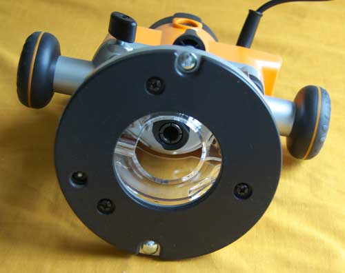 |
This view of the router base
shows another distinct difference
- the use of only three screws
holding the baseplate, instead of
the four used on predecessors.
The "T"-bar mechanism for the
height winder handle can also be
seen (at 8 0'clock).
The two dome-head,
spring-tensioned bolts that hold
the router into the Triton
Router Table (RTA300) are
identically placed, so the
machine remains compatible for
Triton Table use.
|
| Here, the base is removed to
reveal the reason behind the
three-screw fixing.
On the MOF001 model, the height
winder was situated "outside"
the base area, via a dimple in
the casing. This allowed the
baseplate screws to retain
identical positions to those on
its predecessor (TRA001), thus
giving direct compatibility when
mounting under a third-party
router insert, such as a
Rousseau™.
As can be seen in the picture,
having four screws would have
compromised the inclusion of the
winder, which - in this model -
uses the right-hand plunge post
for access.
I do not envisage any
difficulty in re-drilling
third-party inserts, should the
router be required for table use
(other than in the RTA300 Triton
Router Table).
|
 |
 |
The JOF001 baseplate has
identical locating lugs to those
of the MOF001, so will accept the
guide bush insert from the
template kit for that model.
The lugs are visible in this
photograph (at 11 o'clock and 5
o'clock). The picture also shows
the template guide insert in
situ.
|
| This picture shows the MOF001 on
the left and the JOF001 on the
right as a crude comparison.
The most obvious differences
are the "simpler" look and the
lower-set handles of the JOF001.
|
 |
 |
This picture shows the JOF001
directly in front of the MOF001
and has been taken from an
approximation of "eye level."
In this view, the lower-set
handles of the JOF001 are more
obvious, as is the slight
decrease in overall height from
the MOF001. It is also lighter
than the MOF001 at 4.3kg
(9½lbs.).
|
| This close-up shows the
spindle-lock cam, identical to
previous models in its operation
by locking the spindle
automatically when the router is
fully plunged for bit changing.
The only operational difference
with this router is that the
plunge itself is carried out
manually (when using freehand),
or with the winding handle (or
fine height adjuster) when
inverted.
|
 |
 |
This close-up is of the fine
height adjuster, which is turned
clockwise to plunge. Unlike the
two previous models, this adjuster
cannot be brought into use in
conjunction with plunge mode
winding mechanisms, because there
aren't any!
This means that - when used
freehand - the operator has a
choice of plunging freehand and
locking with the plunge-lock
lever, plunging to a
pre-determined depth (using the
turret and depth stop) then
locking, or winding the router
down to the desired depth by
screwing the fine adjuster
clockwise. Once you reach the
required depth, use the plunge
lock lever as "belt and braces."
If you wish to change the bit
after using the fine adjuster,
you are still able to fully
plunge the router to do so, as
the adjuster only restricts
movement upwards (when used
freehand).
The plunge spring is not
accessible from the top, but is
held in place by an ingenious
circlip stack - the first
holding the "T"-bar and the
second - beneath it - holding
the spring in place.
It's a little early to start
describing dismantling
procedures, although I've heard
from Chris Nicholls (also in the
UK) that the plunge spring
cannot be removed on this model,
as it renders the winding
mechanism inoperative. Thanks
for the info, Chris!
|
| So, finally, here's the full
range, showing - from left to
right - the TRA001, the MOF001 and
the JOF001. |
 |
|
Numbered photographs of
TRB001 and logo
courtesy of Triton
Workshop Systems |
|
©Ray Girling, 2000 -
2026

| | |